Lane model
The Lane model includes four major components:
- Lane Topology: the width of a road, the number of lanes, and the mapping of lanes through intersections, merges, and splits.
- Lane Geometry: the shapes of lanes and the positions of their boundaries.
- Lane-Road References: the relationships between the Lane Model and the Road Model.
- Lane Attributes: the attribution applied to lanes and lane boundaries, such as a bus-only lane or turn lane.
Lane topology
Some terms used in this document—including accessors, portals, and surface paths—aren't industry standard. Some companies might use different terms for similar concepts.
In the simplest case, a road in the Lane Model has a consistent lane topology that's defined by accessors and portals. In the figure below, accessors are the cyan lines perpendicular to the road, and portals are the yellow triangles pointing in the direction of travel for each lane on the road.
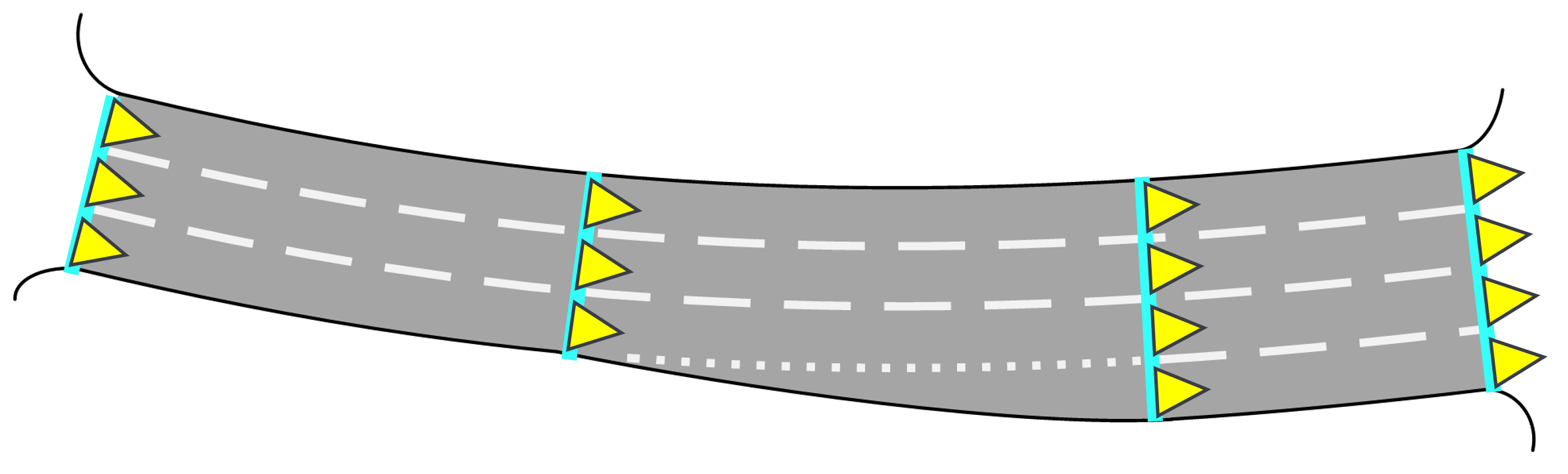
- Accessors define the 3D locations of roads, as shown in the preceding figure. An accessor is a vector in 3D space. The endpoints of an accessor are geo-located with latitude, longitude, and elevation relative to sea level of the applied planetary ellipsoid. Whenever a road changes the number of its lanes, the map captures this change by placing a new accessor on the road where this change begins and placing another accessor where the change is complete.
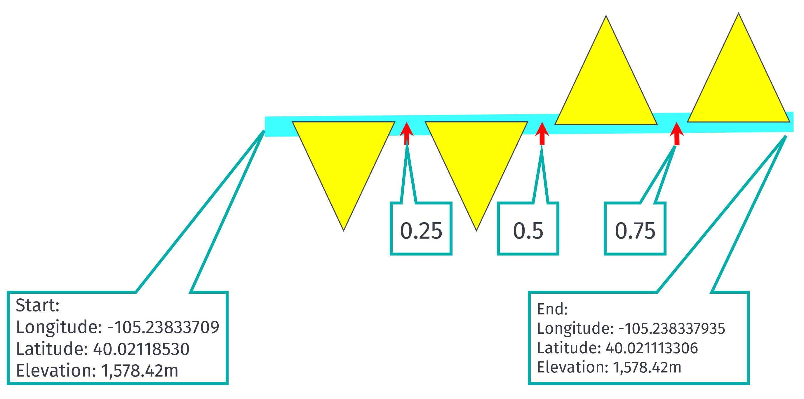
- Portals define the number of lanes on a road and the travel direction of each lane. Parametric points separate portals along accessors that define the relative widths of lanes, without gaps or overlap. This relative width is on a parametric scale of 0-1 where 0.0 and 1.0 are always at the start and end of an accessor. It's not a measure of physical distance. As illustrated in the example below, a road with two lanes in each direction, all of equal relative width, has portal separators at 0.25, 0.5, and 0.75.
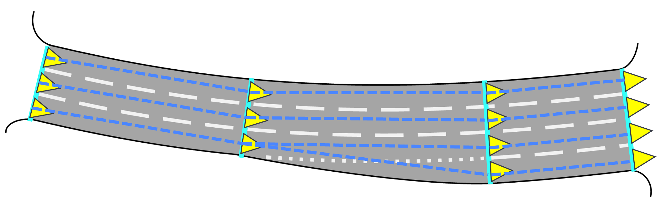
Lane connectivity, which defines each legal and logical path that traffic can take, is another key consideration of lane topology. In the simple case of a road that adds or removes lanes, the lane inputs correlate to lane outputs as shown by the dashed blue lines in the figure below.
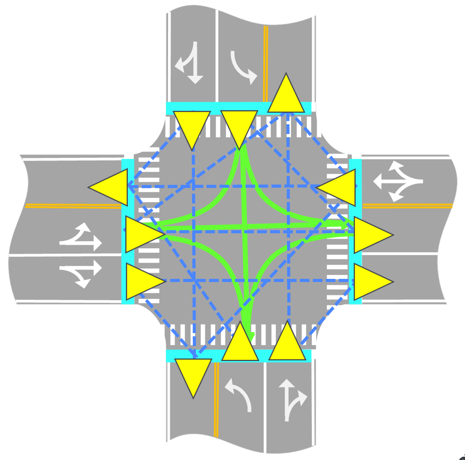
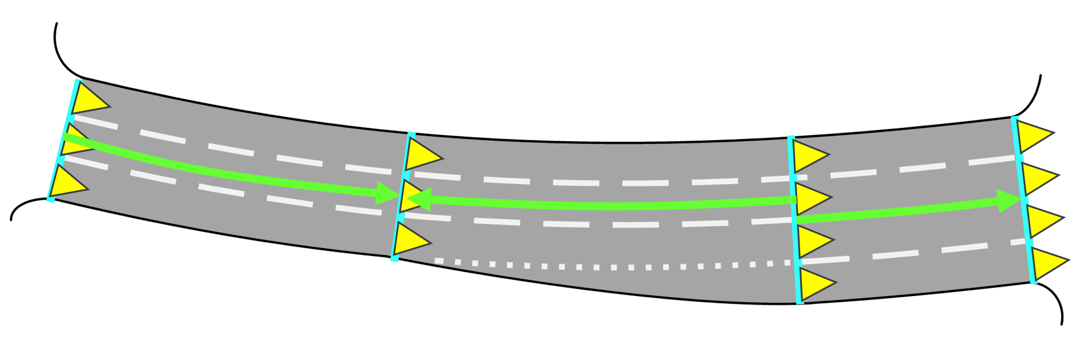
More complex examples of lane connectivity arise at intersections, where three or more roads converge. In the figure below, the dashed lines show the lane mappings, and the portal arrows show directionality. Accessors define where road surfaces meet intersections.
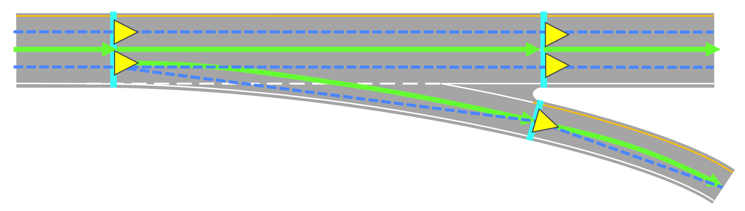
Motorway junctions, such as off-ramps, function like a type of intersection, as shown in the following figure. Lane mappings follow the logical and legal paths that traffic can take. Accessors indicate where off-ramps form and end.
Lane geometry
In the Lane Model, roads are surfaces in 3D space. The start and end points of accessors define the physical width of roads, which in turn define the boundaries of the road.
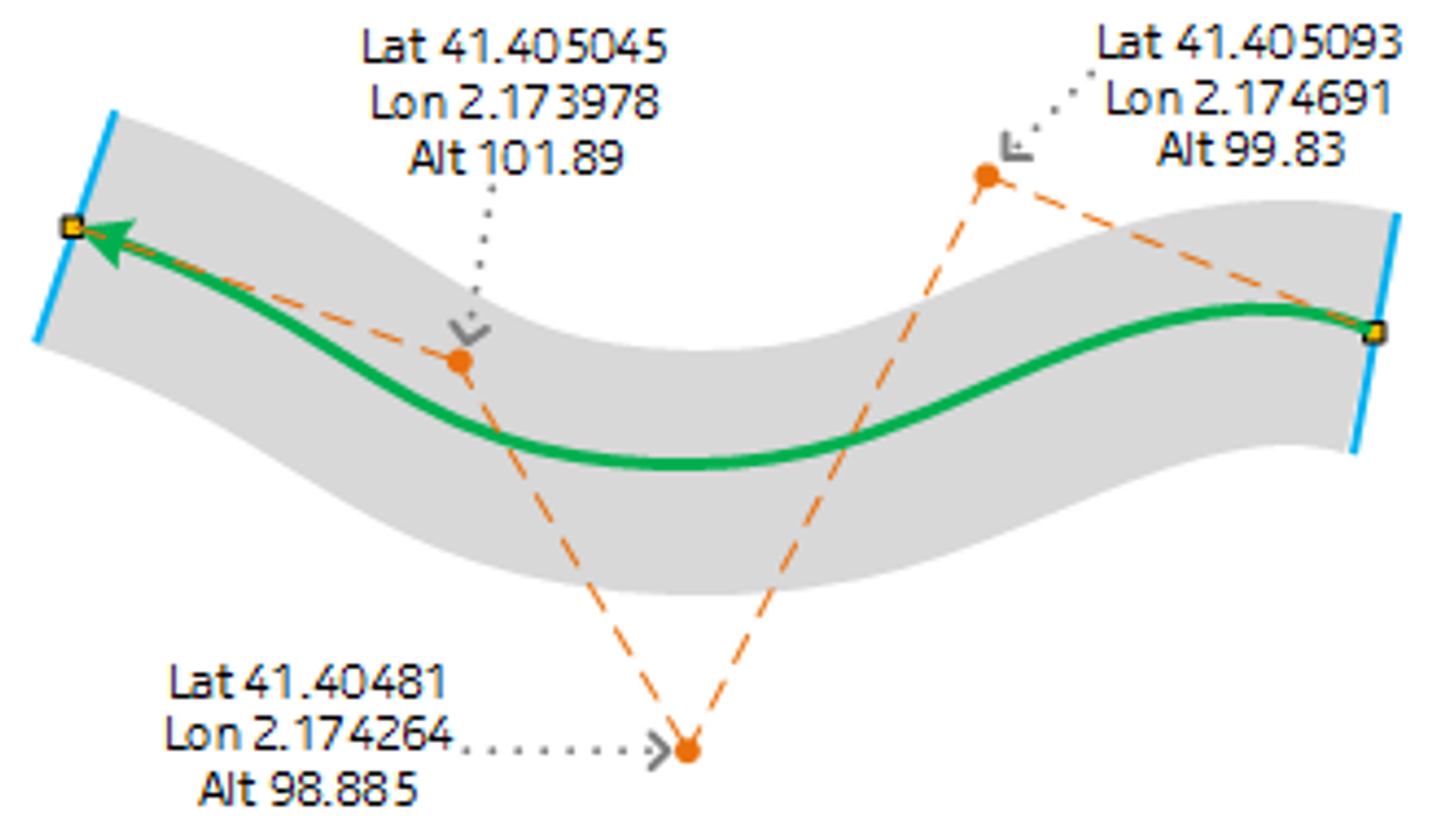
Surface paths also define the bearing, curvature, and slope of road surfaces. Source data defines surface paths using non-linear uniform rational B-splines (NURBS) in 3D space. These NURBS start and end at parametric points on accessors and run along the center of road surfaces and through intersections where traffic flows. The geolocated endpoints of accessors and control points determine the curvature of surface paths, from which you can derive the curvature of roads. As the figure below shows, the green splines with arrows are surface paths on either side of the same accessor. These paths can be offset, but they must have the same tangent and curvature where they meet at an accessor to ensure smooth continuity in the shape of the road.
In the follownig figure, the arrows at the ends of green surface paths point in arbitrary directions, unrelated to the travel direction of traffic. Geo-located control points shape 3D surface paths somewhat like a 3D version of Bezier curves in 2D vector art.
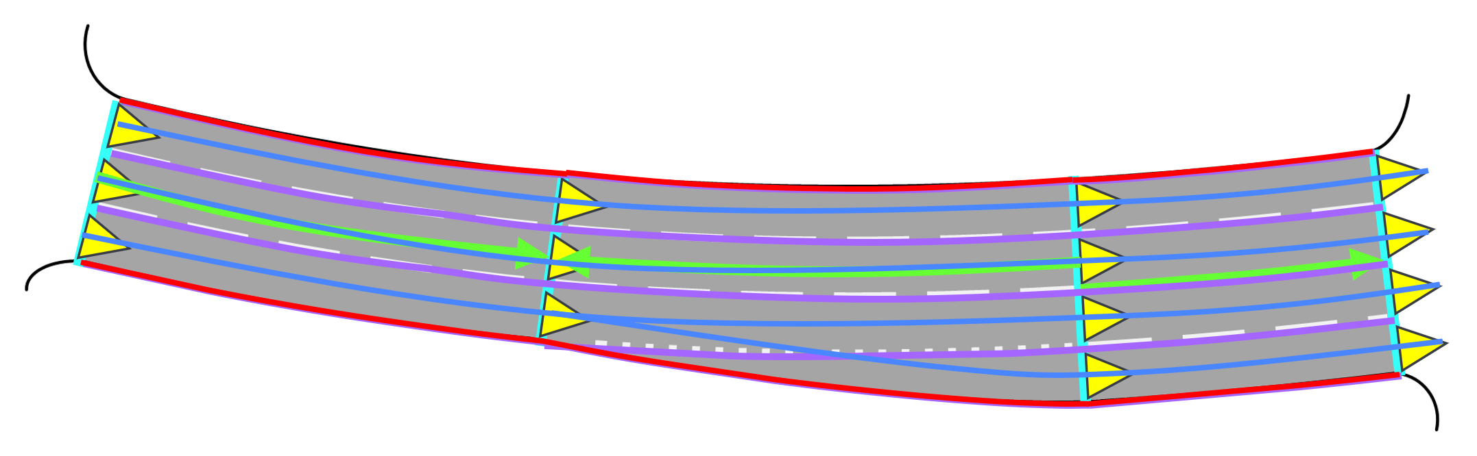
Lane path geometry and lane boundary geometry are also derived from accessors, portals, and surface paths as shown below.
Lane-Road references
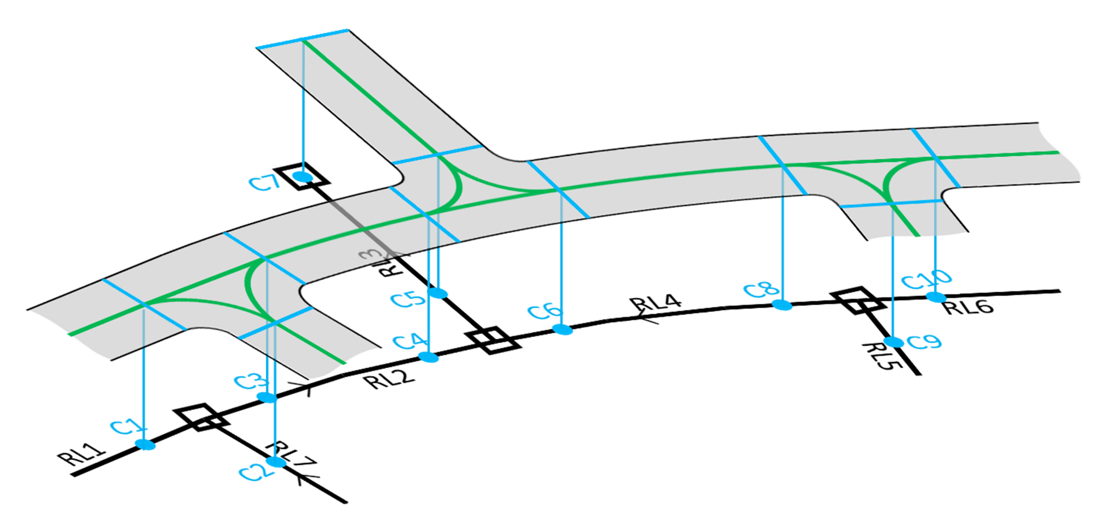
Map data in the Lane Model uses road topology and lane-related data in the Road Model. The Lane Model tracks the corresponding topology segments and nodes in the Road Model to keep map data in the two models in sync. Specifically, the surface paths in the Lane Model refer parametrically to segments (links) identified by unique IDs in the Road Model, as illustrated below.
Lane attribution
The following attributes are commonly applied to lanes:
- Lane Type: including Regular, Acceleration, Deceleration, Turn Lane, Shoulder, and so forth.
- Lane-Level Speed Limit: for cases in which a lane has a different speed limit than the parent road.
- Lane Access Characteristics: for cases when access to a lane differs from access to the parent road. HOV lanes, truck-only lanes, and bus-only lanes are common examples of restricting access to lanes.
- Lane Transition Status: forming and ending. You can derive whether a lane is forming or ending based on its travel direction coupled with its topology.
The following attributes are commonly applied to lane boundaries:
- Lane Boundary Markings: including Style, Color, Material, Width, and Lateral Offset. In practice, Lateral Offset uses a limited number of styles that represent multiple-stripe boundaries: double solid, double dashed, solid-dashed, dashed-solid.
- Lane Boundary Traversal: Can you change lanes? Yes or no left-to-right, right-to-left, or both ways.