Map foundations - topology and geometry
The most fundamental component of a digital road map is the topology representing a road network.
The basic Road Model at HERE uses a simple logical topology consisting mainly of roads, called "links," forming linear connections between intersections, called "nodes," where three or more roads join. The nodes are accurately geolocated in 2D space. Links start, end, and meet at nodes. Links are straight lines that don't follow the curves of actual roads. Hence, the basic Road Model represents the logical topology of a road network but not the physical paths of roads.
By using geolocated "shape points" along links, you can approximate the geometry of road curves with a series of connected line segments called "polylines." These shape points affect the digital representation of road geometry, but they're not part of the logical topology.
Road maps can be further enriched by the inclusion of attributes on links, such as speed limits and direction of travel, as well as geo-located objects like street signs and barriers associated with roads for localization.
In the basic Road Model, the attributes assigned to a link apply to the entire link. In cases where the value of an attribute changes mid-link, such as a change in speed limit between intersections, a "bivalent node" allows the attribute to change between intersections. A bivalent node accomplishes this by connecting exactly two links without an intersection, so a different attribute/value can apply on each link.
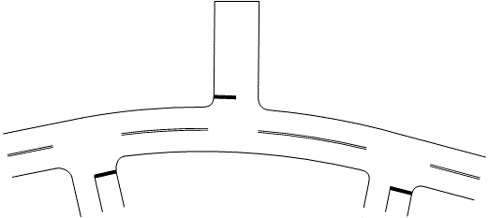
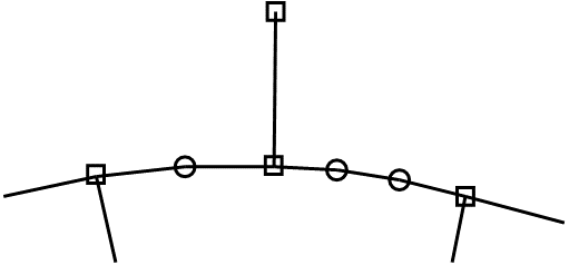
The first figure below represents a real road. In the second figure, the squares are nodes at intersections; the circles are shape points between intersections; and the line segments connecting the nodes are links representing roads.
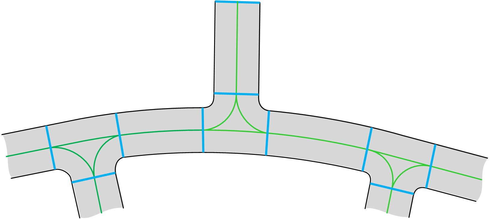
More advanced models replace the concept of a link with that of a "topology segment" and add robust support for individual lanes. Topology segments support parametric attributes that can apply along subsections of roads between intersections, without the need for bivalent nodes to support attributes that change between intersections.
In the Lane Model, NURBS (Non-Uniform Rational B-Splines) are mathematical splines in 3D space that more accurately represents the 3D curves of actual roads. Surface paths using NURBS define the centerlines of road surfaces and lane paths in source data. When publishing map tiles for rendering on a screen, HERE tessellates internal NURBS data. The tessellation process converts 3D splines in the source data into 2D nodes and topology segments/links with shape points. This process also ensures backward compatibility with the basic Road Model and the navigational apps based on them.
Non-navigable geometry can represent cartographic features such as lakes, buildings, railways, rivers, and administrative boundaries. Specifically, line segments that form closed polygons represent cartographic surfaces for land use (mainly parks).
In summary, HERE uses three primary map models to represent road and lane topology, as well as attributes and localization objects associated with roads: the Road Model, the Lane Model, and the Localization Model. HERE HD Live Map is an example of a map product that integrates all three models. For details, see Map models.